About this CAD floor plan
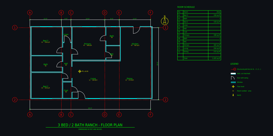
- Overall size
- 15.3 × 9.1 m
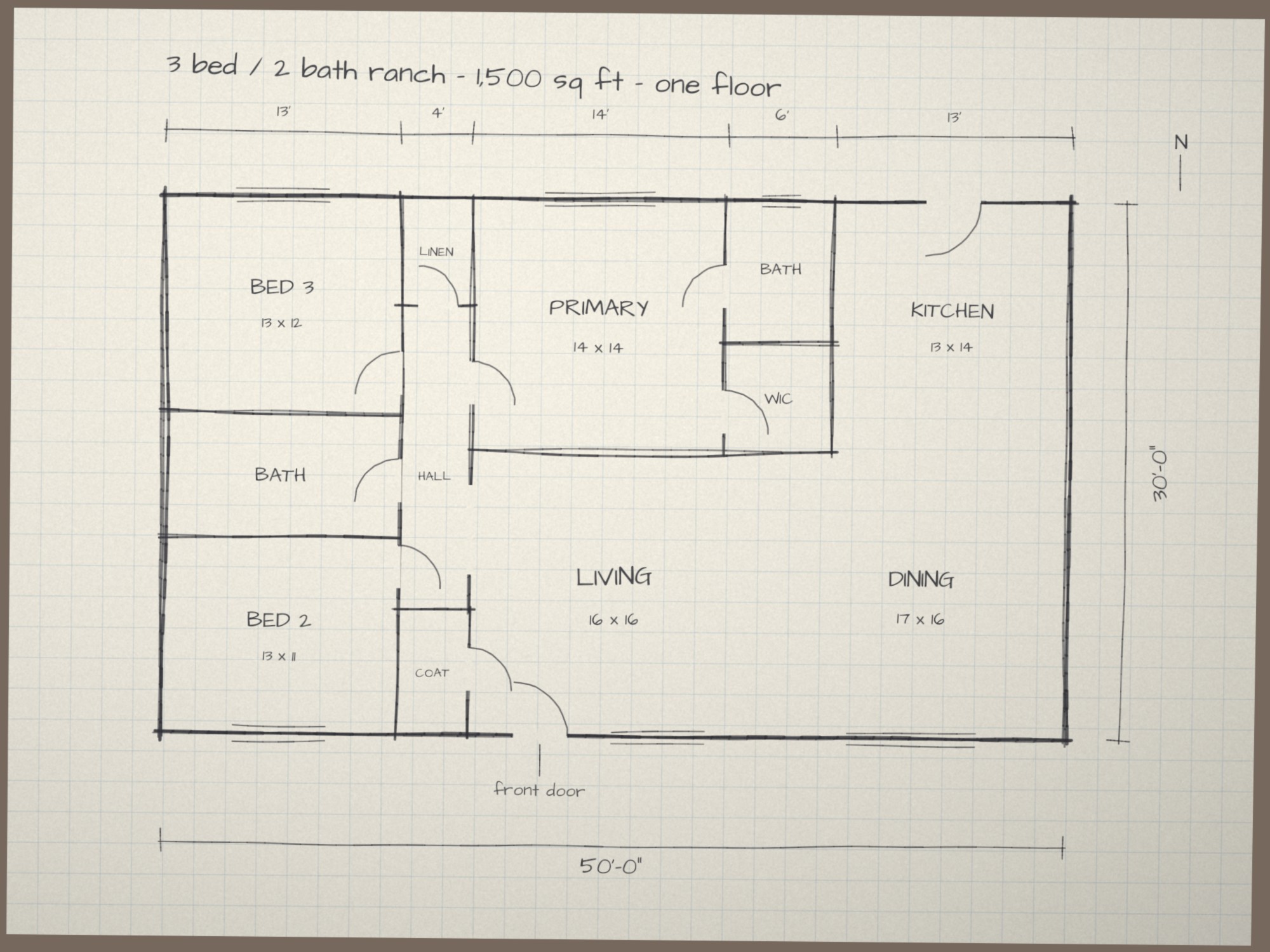
- Drawn from
- a photo / sketch of a plan
- Drafting time
- 3 min, 4 versions
- Files
- DXF (layered), 3D view; DWG and scaled PDF in the studio
- Published
- November 3, 2026
Rooms
- Bed 3
- Bath
- Bed 2
- Linen
- Hall
- Coat
- Primary
- WIC
- Kitchen
- Living
- Dining
The brief
The drafter's notes
What the AI drafter reported when it finished, unedited.
I changed nothing in the drawing this round. I checked the whole plan against your sketch and found no wall missing, off or added. The 85 % figure measures something other than my drawing, which is why I left it.
- What I checked: on the full overlay, every wall on your sketch has my wall drawn on it, including the linen and coat closets, primary bath, WIC and the partial hall walls. 99 % of my wall lines sit on the sketch's lines, and none are off them.
- Why it stays at 85 %: it compares my plan with the walls found in the second measuring pass, the one run after I set the scale. That pass found only 6 walls instead of 14, merged and broken. One of them, W5, runs through the open Dining area where the sketch has no wall, most likely a graph-paper line.
- What I tried: telling the check to ignore W5 lowered the figure to 84 % instead of raising it, so I undid that.
- Why I didn't add walls: adding walls to raise the number would put walls in the plan that aren't on your sketch.
The rest of the drawing is the same as in my last handover:
- Size and grid: 50'-0" x 30'-0", with grid bays across of 13', 4', 14', 6' and 13'.
- Rooms: the 12 rooms from your sketch, with 10 doors and 6 windows.
- Annotation: dimensions in feet and inches, room schedule and legend.
- Layers: A-WALL and A-WALL-PATT (walls), A-DOOR (doors), A-GLAZ (windows), A-GRID (grid), A-ANNO-DIMS (dimensions), A-ANNO-TEXT (text), A-ANNO-SYMB (symbols).
Assumptions, unchanged:
- Areas are your written room sizes. Rooms without a written size have no area, so the schedule totals 1,205 sq ft, not the 1,500 sq ft in your title.
- Door widths, window widths and door hinge sides are typical values or set by eye.
Want a plan like this for your own project?
Upload a photo of your hand sketch or printed plan and the drafter draws it as a layered, dimensioned CAD floor plan in a few minutes. Change it by chat or with CAD tools, see it in 3D and download DXF, DWG and a scaled PDF. Plans from $12 a month; some new accounts get their first drawing free.
Tools used for this drawing
- Sketch to CADUpload a photo of a hand sketch and watch an AI drafter redraw it as a layered, dimensioned CAD floor plan.
- Image to DXFConvert a floor plan image (JPG, PNG, WebP, HEIC, screenshot or photo of a printed plan) into a layered DXF with walls, doors, windows, dimensions and room areas.
- Floor plan to DWGGet an AutoCAD DWG floor plan from a picture, a sketch or a few sentences.
More community floor plans
 # Architectural Design Brief – Mixed-Use Building…
 Barndominium 40 x 64 ft: 3 bed, mudroom, walk-in pantry
 House + backyard ADU on a 40 ft wide lot: 3-bed home, 1-bed ADU
 Duplex on a 30 ft wide lot: two 2-bed units, shared wall
 Modern farmhouse 52 x 36 ft: 3 bed, mudroom, walk-in pantry
 Narrow house on a 20 ft wide lot: 2 bedrooms, office, 1 bath
AI concept drawing: check dimensions and have a licensed architect or engineer review a plan before you build or apply for a permit.