About this CAD floor plan
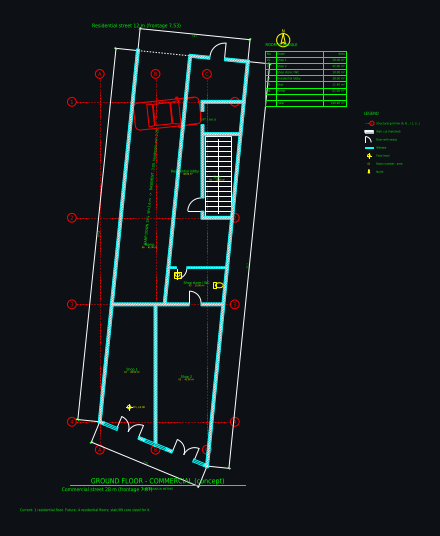
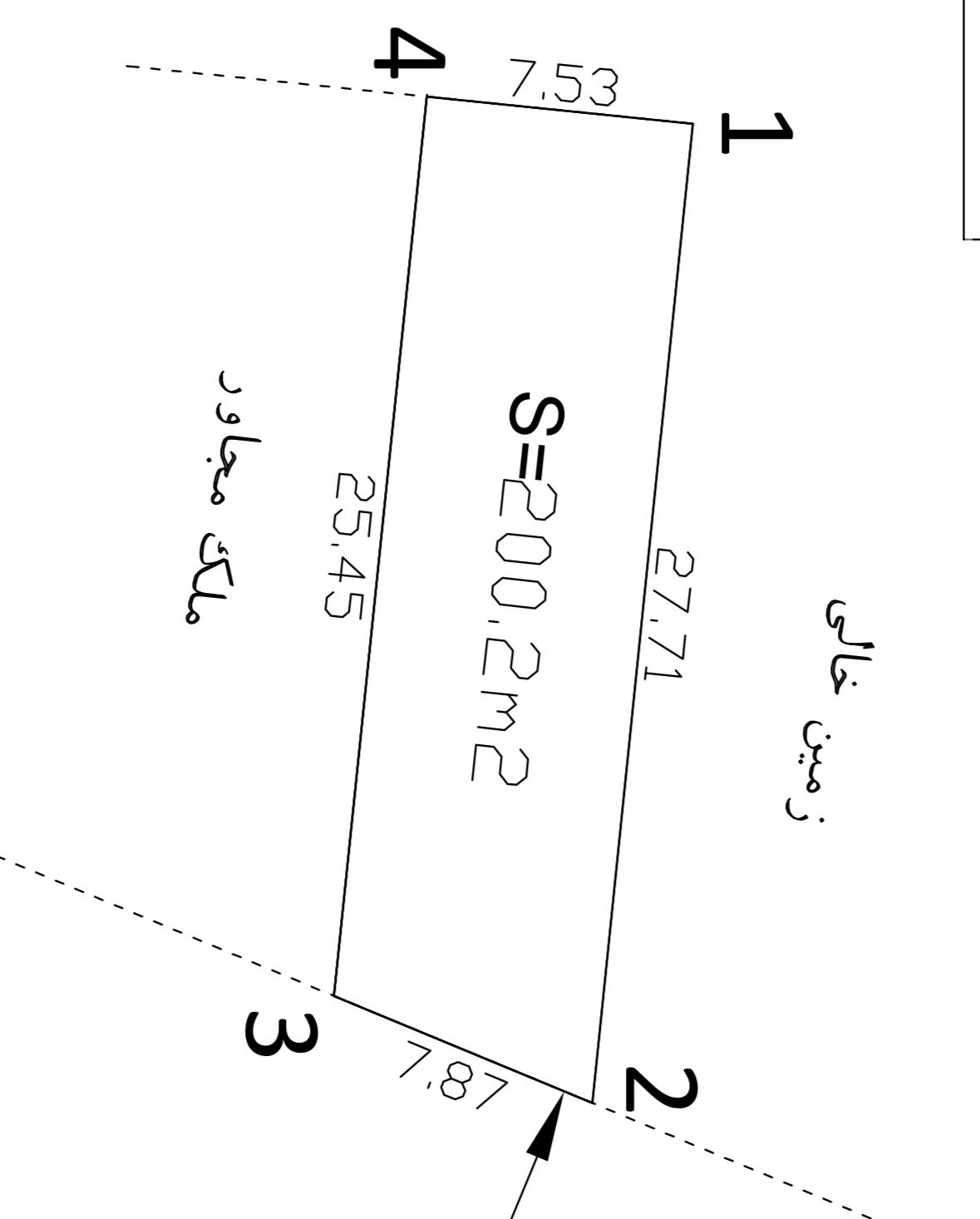
- Overall size
- 10.09 × 28.31 m
- Drawn from
- a photo / sketch of a plan
- Drafting time
- 1 min, 2 versions
- Files
- DXF (layered), 3D view; DWG and scaled PDF in the studio
- Published
- November 3, 2026
Rooms
- RAMP DOWN 15% W=3.6 m -> BASEMENT -3.00, headroom min 2.20
- LIFT 1.6x1.6
- Shop 1
- Shop 2
- Shop store / WC
- Residential lobby
- Stair
- Ramp
- Commercial street 28 m (frontage 7.87)
- Residential street 12 m (frontage 7.53)
- Current: 1 residential floor. Future: 4 residential floors; stair/lift core sized for it.
The brief
# Architectural Design Brief – Mixed-Use Building in Minoodasht, Iran Act as an experienced architectural designer and space-planning specialist. Develop a practical, dimensionally coordinated architectural concept and floor plans for a mixed-use building based on the following project brief. ## 1. Project Information - **Location:** Minoodasht, Golestan Province, Iran. - **Plot geometry:** Irregular quadrilateral plot. - **Plot side lengths:** - Street frontage A: 7.87 m - Street frontage B: 7.53 m - Party wall side C: 27.71 m - Party wall side D: 25.45 m - The two long sides (27.71 m and 25.45 m) are fully shared party walls with neighboring properties. - The property has access from two streets. - Street width along the 7.87 m frontage: 28 m. - Street width along the 7.53 m frontage: 12 m. - **Important:** Use the original plot drawing/image as the primary reference for plot shape, orientation, and side identification. Do not assume the plot is rectangular or that the listed dimensions alone fully define its geometry. ## 2. Building Program Design the following building configuration: 1. Basement -1: Entirely dedicated to vehicle parking and parking circulation. 2. Ground floor: Two adjacent commercial units. 3. First floor: One luxurious two-bedroom residential apartment. The current permitted/planning scenario includes only one residential floor above the commercial ground floor. However, the anticipated physical/structural development scenario may include four residential floors above the commercial ground floor. Therefore, develop the initial architectural layout for: - One basement parking level - One commercial ground floor - One residential floor with one luxury two-bedroom apartment Also consider the potential future vertical extension to four residential floors above the commercial ground floor. Clearly distinguish the currently intended design from the future development scenario. ## 3. Access and Circulation - Commercial entrance must be from the 7.87 m street frontage. - Residential entrance must be from the 7.53 m street frontage. - The basement parking ramp must be located entirely within the property. - Provide a straight, single-direction ramp alignment with a practical vehicle approach and transition zones, subject to code-compliant slope and headroom. - The ramp must be accessed from the 7.53 m residential street frontage. - Keep the residential entrance, commercial entrances, and parking ramp entrance clearly separated. - Locate the main staircase and passenger elevator directly next to each other. - Position the staircase and elevator along the right-hand long side of the plot, as shown in the original reference drawing. - Preserve independent and secure access to the residential floor. - Avoid unnecessary circulation space and conflicts between pedestrians and vehicles. ## 4. Basement Parking Design Design the basement as a fully functional parking level. Requirements: - Provide the maximum practical number of standard parking spaces without compromising usability. - Prioritize comfortable parking maneuvers, easy entry and exit, and unobstructed circulation. - Avoid tandem parking, blocked vehicles, and parking spaces that obstruct other parking spaces. - Use realistic parking stall dimensions and aisle widths appropriate to Iranian regulations. - Consider structural columns, walls, elevator core, staircase, ramp, turning paths, and vehicle clearances. - Clearly indicate parking dimensions, aisle widths, ramp width, ramp slope, direction of travel, and headroom. - Provide a straight ramp within the site boundaries. - Do not claim a parking capacity unless it is verified against the actual geometry and circulation requirements. - If a comfortable, non-blocking layout is not feasible, explain the constraints and propose the best alternative. ## 5. Ground Floor – Commercial Design two adjacent commercial units. Requirements:
The drafter's notes
What the AI drafter reported when it finished, unedited.
plan.dxf now has a concept ground floor (commercial level) drawn inside the true plot outline. It is a design concept, not a measured survey: your sketch is a site plan with only the plot's boundary lengths and no building. I compared the preview once and fixed the car on the ramp, which was drawn crossways. The re-run after that fix printed no errors, but I have not checked that second preview.
What is in the drawing:
- The plot outline drawn to your four lengths, 7.87 / 27.71 / 7.53 / 25.45 m (shape scaled from the sketch at 42.7 px/m).
- Two shops opening onto the 7.87 m street:
- Shop 1 about 28 m²
- Shop 2 about 42 m²
- a shared store/WC of about 10 m², reached from Shop 2
- A residential lobby with its door on the 7.53 m street.
- The stair (16 steps) and a 1.6 x 1.6 m lift side by side on the right-hand (east) party wall. The core is sized for the future four residential floors.
- A straight one-way ramp, 3.6 m wide, along the west party wall, entered from the 7.53 m street through its own garage door, separate from the residential door.
- Room tags and a room schedule, the plot dimensions, the street names, the floor level, a north arrow, the title and a legend.
- Layers: A-WALL, A-DOOR, A-GLAZ, A-FLOR-STRS, A-FLOR-FIXT, A-FURN, A-GRID, A-ANNO-TEXT, A-ANNO-DIMS, A-ANNO-SYMB.
Assumptions:
- North is up on your sketch, and corner 3 is the origin.
- The room areas are estimates, not computed from the drawn walls.
- The 15% ramp slope and the basement at -3.00 are assumptions. At that slope the ramp runs about 17 m and passes under the shops. It still needs checking against the code and the actual headroom.
- Party walls are 0.20 m thick and interior walls 0.12 m.
Not drawn yet:
- The basement parking level. I have not claimed a number of parking spaces because none has been checked against the real geometry.
- The first-floor two-bedroom apartment.
- The future floors, other than the note on the drawing and the core sized for them.
Your brief stops partway through section 5, so any ground-floor requirements after that point are not included. A message with the rest of the brief, or the go-ahead for the basement and first floor, is enough for me to continue.
Want a plan like this for your own project?
Upload a photo of your hand sketch or printed plan and the drafter draws it as a layered, dimensioned CAD floor plan in a few minutes. Change it by chat or with CAD tools, see it in 3D and download DXF, DWG and a scaled PDF. Plans from $12 a month; some new accounts get their first drawing free.
Tools used for this drawing
- Sketch to CADUpload a photo of a hand sketch and watch an AI drafter redraw it as a layered, dimensioned CAD floor plan.
- Image to DXFConvert a floor plan image (JPG, PNG, WebP, HEIC, screenshot or photo of a printed plan) into a layered DXF with walls, doors, windows, dimensions and room areas.
- Floor plan to DWGGet an AutoCAD DWG floor plan from a picture, a sketch or a few sentences.
More community floor plans
 Barndominium 40 x 64 ft: 3 bed, mudroom, walk-in pantry
 House + backyard ADU on a 40 ft wide lot: 3-bed home, 1-bed ADU
 Duplex on a 30 ft wide lot: two 2-bed units, shared wall
 Modern farmhouse 52 x 36 ft: 3 bed, mudroom, walk-in pantry
 Narrow house on a 20 ft wide lot: 2 bedrooms, office, 1 bath
 Narrow house on a 25 ft wide lot: 3 bedrooms, 2 baths, courtyard
AI concept drawing: check dimensions and have a licensed architect or engineer review a plan before you build or apply for a permit.